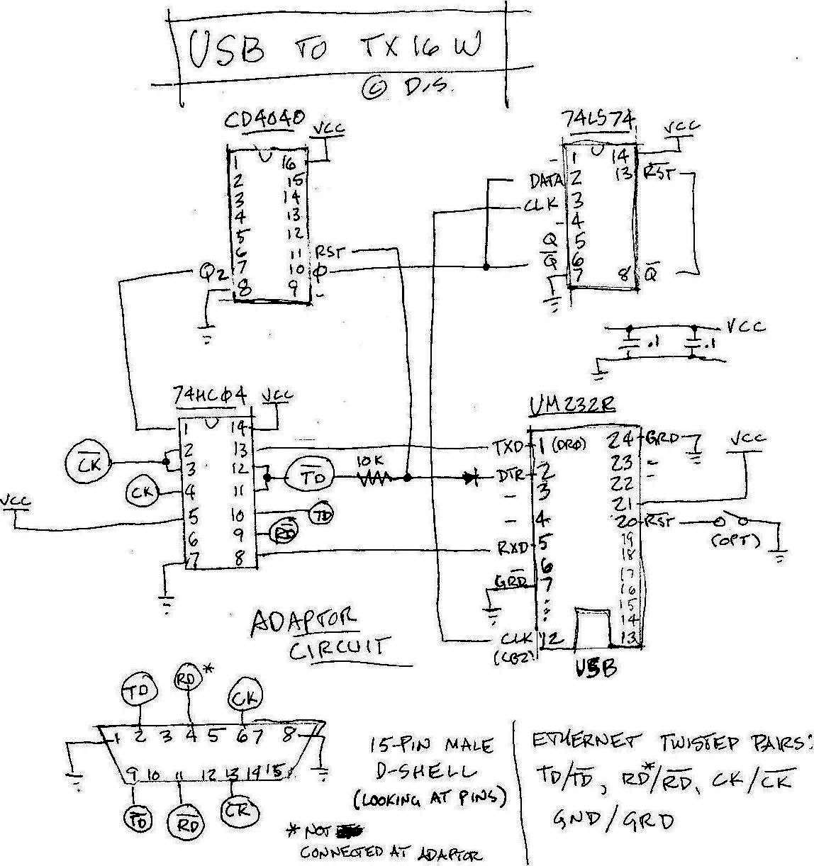
The Schematic:
Hardware:
Misc: Electronics:
ICs:
UM232R – USB to Serial interface
74HC04 - High Speed CMOS Hex Inverter
CD4040 – CMOS Ripple Counter
74LS74 – LS Flip Flop
The Schematic:
Messy Details:
The interface is just a necessary evil needed to run the
software.
I needed to derive a synchronous clock from the UM232R. Because
of
the speed of the UM232R clock, I used an LS flip flop to get
the clock slow enough for the cmos CD4040 ripple counter. The diode and
resister are used make sure the derived clock is in proper phase. This
is done when the interface is initialized.
There are better ways to do all of this. But these are the
parts I had, and
it works . (Perhaps there’s a UM232R like device that generators a
proper clock. Don’t know.)
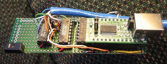
Also, I know the hex inverter is far from an ideal RS-422 interface chip, but it works. (Note that the hex inverter in the photos of my boards is wired differently than that shown on the schematic.)
Please see other page about the software needed: special TX16W boot disk, the PC disk Emulation software and the various ISO images of the TX16W disks including a modified version of Typhoon.
I CAN’T GUARANTY THAT THIS CIRCUIT or THE SOFTWARE WILL INSTALL or WORK FOR YOU. NOR CAN I SUPPORT THE DESIGN OR THE SOFTWARE.